

With as many as 82 bodies of victims of the Balasore train crash which occurred nearly a week ago remaining, Odisha government Thursday held discussions with the officials from West Bengal, Bihar and Jharkhand seeking help in early identification and disposal of the human remains preserved.
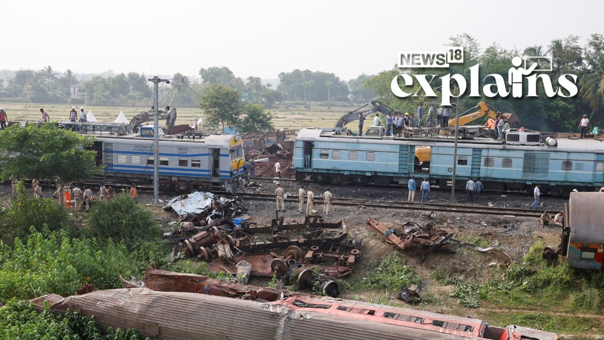
A collision between three trains in Odisha resulted in a tragic loss of over 280 lives, with over 1,000 individuals sustaining injuries. The incident occurred when a passenger train derailed onto an adjacent track and was subsequently hit by an incoming train. The collision also affected a stationary freight train in close proximity.
After the horrific incident, an investigation has been launched into what led to it. Amid the case, let’s understand the normal functions and operations of a station’s Route Relay Interlocking (RRI) signaling system. Later, we will delve into what might have led to the crash:
How it Works
In a properly functioning signaling system, the Signal Operator or Station Master (SM) is unable to give a signal for a train to enter a loop line unless the loop line is unoccupied, sources explained.
Station-level interlocking systems are designed to ensure the safe setting and operation of routes (train paths) through a mesh matrix of relevant switches/points, track occupancy detection, and signal aspects.
Even in old mechanical systems, conflicting routes cannot be set and signaled.
Route Relay Interlocking (RRI) and Electronic Interlocking systems provide even greater robustness with built-in redundancy. Accidents typically occur due to a combination of human and system errors.
For a fast express train to run at high speed on the main up/down line, all points/switches on the route must be set, locked, and detected in the normal (N) position.
The points/switches are operated to N or R (Reverse) through a Point Machine (PMC), which is mostly motorized and electrical. In some areas with heavy flooding during the monsoon season, pneumatic point machines are used.
The PMC is controlled by the RRI system based on the commands of the SM. The SM sets the desired route and signal aspect using buttons on the Station Control Panel. The RRI validates the commanded route and allows it only after verifying that there are no conflicting routes, movements, or track occupancies already set and in force. This is determined by detecting train arrivals and pass-throughs using track circuits.
Once the route is validated and allowed based on the current conditions and status of track occupancies and other train movements (especially in large yard layouts), the requested route is set. The RRI sends commands to the required Point Machines, which physically move the points to the necessary N or R positions.
The Point Machines also mechanically lock the points in the required positions. This process is the actuation of the action at the point/switch.
To ensure safe train movement, it is important to have accurate detection in the signaling system. The positioning of the points or switches, whether in the Normal (N) or Reverse (R) position, is detected by robust electrical contacts.
These contacts provide independent detection for each movable tongue of the point or switch. Additionally, the mechanical locking of the points is also detected through another set of electrical contacts. This locking mechanism prevents any unintended movement or separation of the point tongues caused by the forces exerted by passing train wheels.
For each point along the designated route, the system ensures that it is set and locked correctly, with the position and lock detections functioning properly.
Only when all points on the route are successfully set, locked, and their positions and locks are accurately detected, the corresponding signals on that route are set to display the appropriate green or yellow lights. If any of the point conditions fail, such as defective locks or position detections, the route cannot be set, and there will be a failure in the signal operation.
This fail-safe mechanism ensures that any failure in the system triggers a safer response, leading to more restricted or stopped train movements.
The signaling system relies on precise detection mechanisms to confirm the correct positioning and locking of points along the route. Only when these conditions are met, the signals are set accordingly, and any failure in the detection process leads to a safer operational state.
Once a route is successfully set, it remains active and locked, preventing conflicting movements until the actual train movement is completed. This is determined by the occupancy and release of track sections, which are detected through track circuits.
Once the set and signalled route has been successfully traversed, it is released and no longer locked. This allows other routes that were previously in conflict with the completed route to be set and permitted.
A Signal Operator (SM) has the ability to cancel a signal or route setting if there are changes in train movement requirements or the need to set a conflicting route for another movement.
However, when a route is already set and a specific signal aspect is already displayed, cancelling it by the SM will immediately change the signals to a more restrictive aspect or red/stop.
However, the Route Relay Interlocking (RRI) system will wait for approximately 3 minutes to verify that the signalled train has not entered the signalled section before releasing the set route and allowing other conflicting movements. If the train has entered the signalled section before this 3-minute release time, the set route cannot be cancelled until the train movement is completed.
For example, if the SM cancels the route or signal when the train and driver have already crossed the signal or are close to crossing the green/yellow signal and cannot stop ahead of it, the train will continue into the signalled section despite the cancellation.
It’s important to note that multiple non-conflicting routes and movements can be set and active simultaneously, especially in larger yards like Chennai Central, where the operational requirements are more complex.
Division of Responsibilities
In the functioning of railway signaling systems, there is a division of responsibilities between the Signaling Department and the Traffic Department.
The Signaling Department is responsible for the installation, maintenance, and repair of all RRI systems, including signals, point machines, cables, correct wiring, and power backup systems such as batteries.
In larger stations like Chennai Central, there may be a dedicated team of signaling maintenance staff. However, in smaller way-side stations like Balasore, there is typically one common team that covers multiple stations. This team performs scheduled maintenance tasks and responds to failure repairs when called upon, the sources explained.
On the other hand, the Traffic Department, a non-technical department, is responsible for station operations. The Station Master (SM) and their staff control train movements using the Station Control Panel facilities, which serve as the human operator interface for the RRI and signals.
In the past, the Traffic Department staff operated mechanical signals and points from lever cabins located near the signals, communicating with the SM through magneto phones. With the transition to RRI, the operation of signals and points is now centralized and controlled by the SM using buttons on the Station Control Panel, eliminating the need for lever cabins. This modernization has made operations more convenient for the Traffic Department staff.
However, it is important to note that in case of RRI failure, such as the system being unable to set a route due to a failure in detecting the position or lock of any point in the yard, there are manual fallback procedures outlined in the Station Working Manuals.
These procedures require the SM and the Traffic Department staff to physically go to the points, secure and lock them manually in the desired position (N or R), and then permit train movements. This is a responsibility that falls upon the SM and the Traffic Department in such situations.
However, the manual fallback procedure can be physically demanding and time-consuming for the Traffic Department staff. In situations where a point is defective and the RRI system cannot set a route, the Traffic Department staff should personally be present at the defective point to manually secure and lock it in the required position (N or R).
They would then communicate this information to the Station Master (SM), and the train would be allowed to proceed based on a manual written authority rather than a signal indication. This ensures safety, albeit with slower movements.
Walking to a point that is a kilometer away in outdoor weather conditions and manually securing and locking it for each train movement can be tiring for the staff who have become accustomed to the convenience of the RRI system.
Additionally, issuing paper-based movement authorities for each train adds further administrative burden. To mitigate these challenges, it is common for a Traffic Department staff member (or even an unofficial signaling staff member) to be stationed at the problem point.
They would manually set, lock, and communicate the position (N or R) to the SM, who would then instruct a signaling staff member in the station to bypass the detection interlock for that particular point.
This bypassing allows the system to simulate proper point detection, ensuring that the route can be set and train movements can continue while the point failure is being rectified.
However, it’s important to understand that these temporary measures are taken to maintain operational continuity until the point failure can be repaired and the system can resume normal functionality.
The sources noted that bypassing the point detection interlock in the RRI system without proper authorization is a shortcut. It can introduce human error and increase the risks associated with train operations.
On Odisha Train Accident
The Odisha train accident appears to have occurred due to a combination of factors, as per the sources:
Point failure: The point leading to the loop line experienced a failure, which could involve issues with the motor, movement, position, lock, or detection of the point.
Unauthorized shortcut: Due to traffic pressure and the unavailability of a “Time Block” for rectifying the point machine, an unauthorized manual bypass of the point detection interlock in the RRI system was resorted to. This shortcut was taken to expedite train movements but introduced additional risks.
Incorrect communication and signal setting: The risky point detection interlock bypass led the RRI system to believe that the point was set and locked correctly in the Normal (N) position for high-speed passage on the main line. As a result, a Green signal was given to the Coromandal train instead of a Yellow signal.
Manual errors or lapses: It is possible that the actual point was set incorrectly, either to the Reverse (R) position but communicated as Normal (N) by the person at the point, or the manual locking of the point was not properly executed. This could have caused the point tongues to move under the high-speed movement of the train, resulting in the diversion of the Coromandal train to the loop line.
Regarding the station’s signaling system, it is mentioned that the station is supposed to have an Electronic Interlocking System (EIS) instead of a Route Relay Interlocking (RRI) system. The EIS utilizes electronics and PLCs (Programmable Logic Controllers) to replace traditional relay-based logic, offering triple redundancy and reduced wiring. However, it is noted that relays are still present at key operating points in the EIS, such as for moving the tongue motor and locking it in position.
Additionally, it is mentioned that there was some ongoing work at the signal point where the accident occurred, and a manual override was performed. This aspect has not received significant coverage in the media thus far, the sources said.